AUTOMATED INDUCTION CHARGING SYSTEM FOR ELECTRIC VEHICULES
Preparatory Class Project for Highest French Engineering Schools
I - Introduction
With the development of electric vehicles in recent years, they seem to be occupying an increasingly significant presence in our cities, along with the charging stations found in our parking spaces. However, as the demand continues to grow, it appears impractical to equip the majority of parking spaces with wired charging stations, as they are bulky, unattractive, and highly unreliable due to users' lack of care. Additionally, the advent of autonomous vehicles in a few years will require the creation of systems capable of charging these vehicles without human intervention. Various solutions have already been explored to autonomously charge these vehicles. Some propose the use of mechanical arms that automatically connect the charger to the vehicle, but these systems are cumbersome, expensive, and even more complex to maintain than existing charging stations, making it challenging to envision their implementation in urban areas. Others suggest inductive charging, which is much easier to integrate into parking spaces and does not involve moving parts. However, it offers a lower efficiency and limited charging speed. Therefore, the ideal solution would be a high-efficiency, high-power, compact system that requires minimal maintenance for municipal authorities, ensuring their proper operation and widespread adoption.
II - State of the Art
The development of infrastructure related to the popularization of electric vehicles makes the implementation of induction charging systems in our cities a relevant consideration. While wired charging stations are typically the chosen solution, they come with certain limitations such as their bulkiness, mechanical wear, and lack of automation, requiring human operators. This could pose challenges, especially with the rise of autonomous vehicles. Therefore, the concept of using induction charging is being explored by the industry, including our contact at Stellantis. We have focused on examining how the positioning of the two coils in this system affects its performance. Taking this into account, we have designed an automated positioning system with the aim of achieving ideal conditions for charging.
III - The Prototype
III.1 - Block Diagram

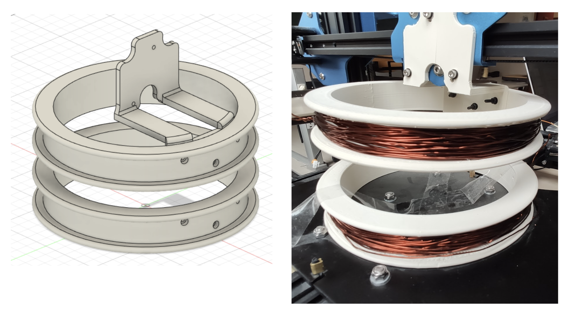
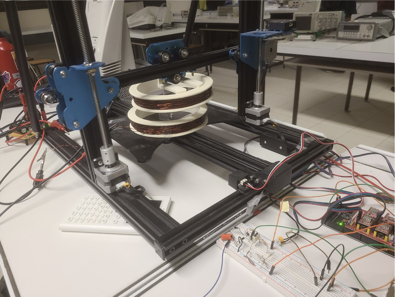
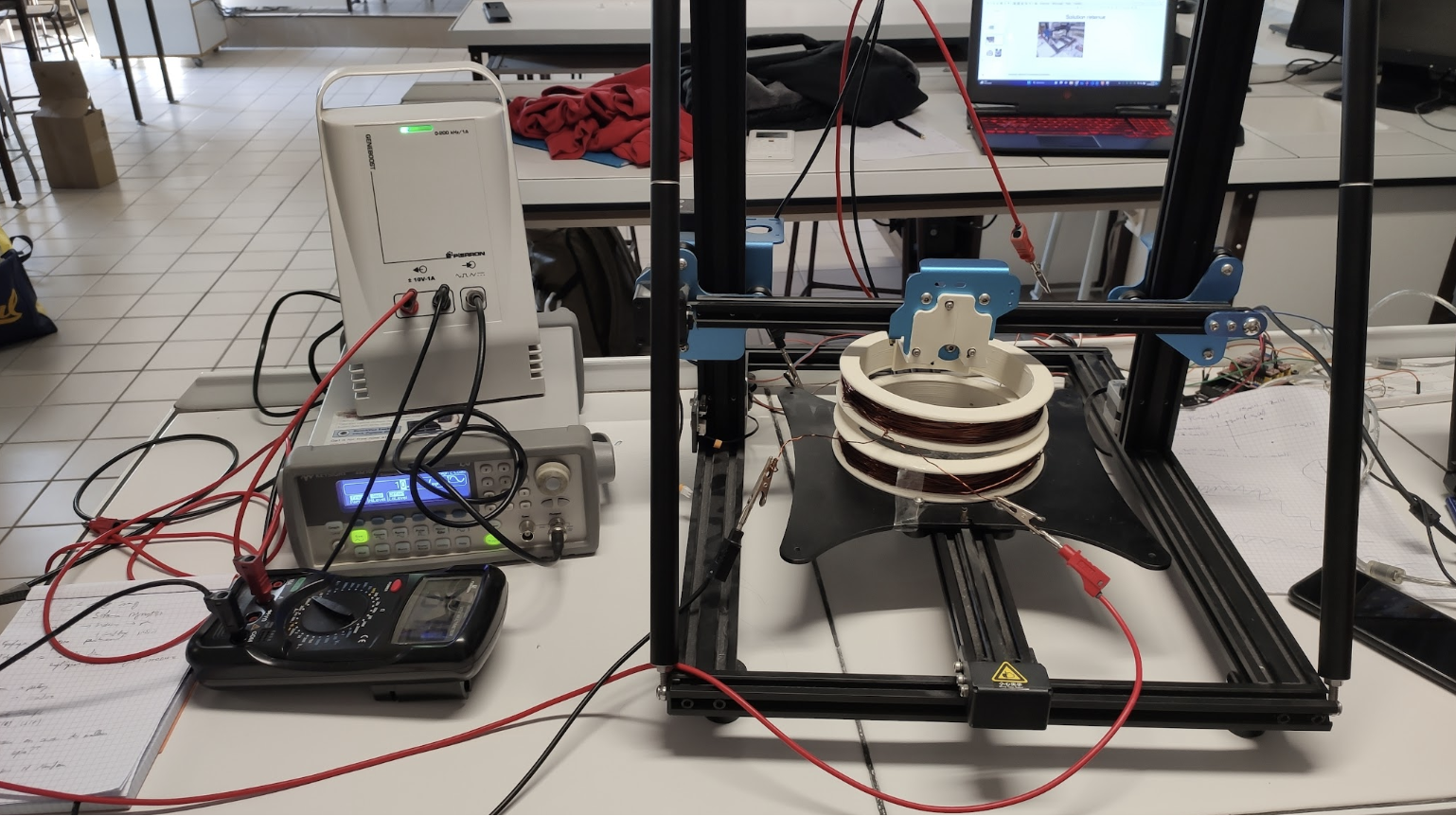
Two coils are placed on two parallel planes: one, located in the parking area, is stationary, while the other, positioned beneath the vehicle, is mobile along two perpendicular axes. In our model, both mobile axes utilize pulley-belt systems, with each pulley driven by a stepper motor.
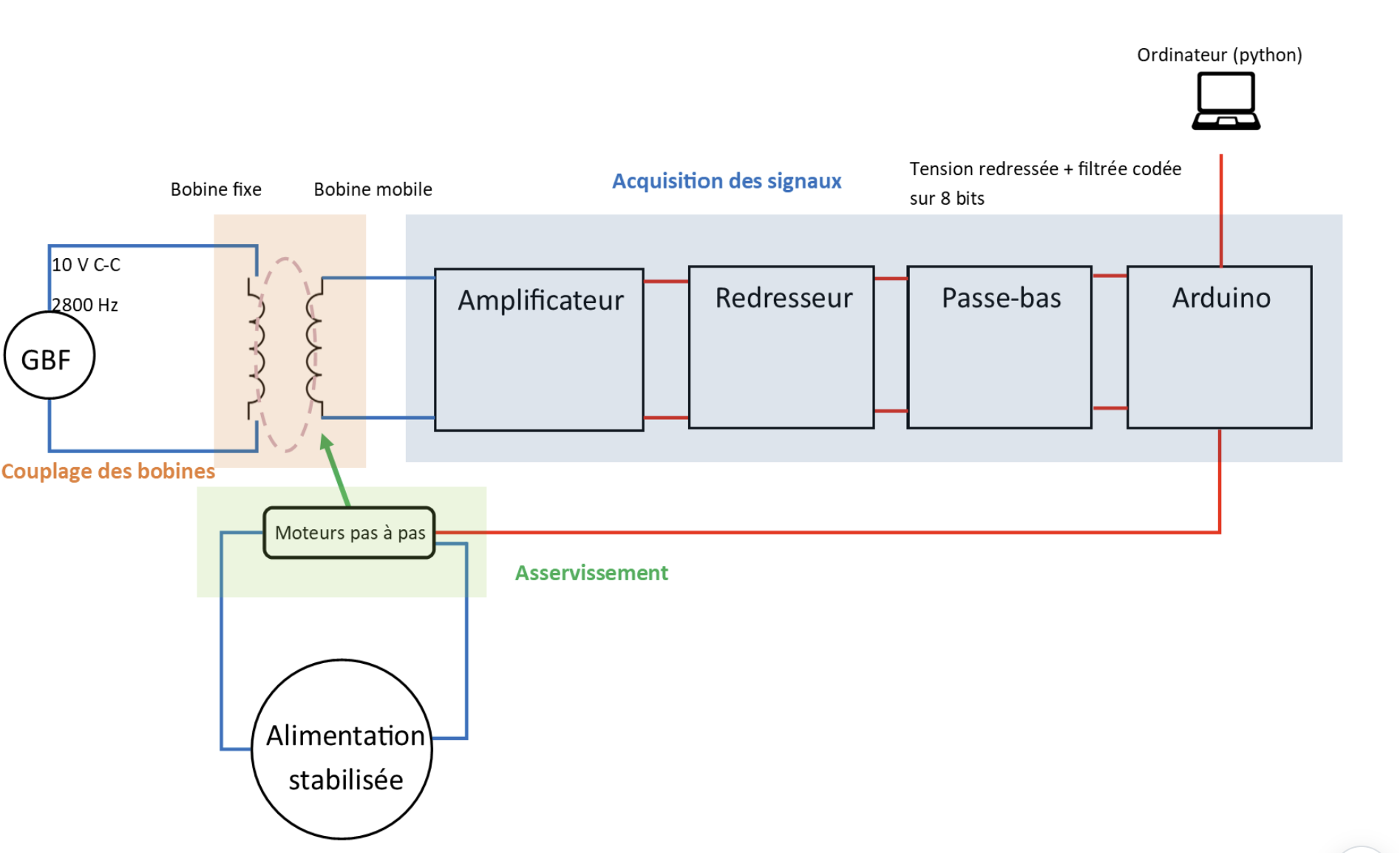
Three main components stand out in the project: The coupling of the coils, the control of the coil positioning, and the acquisition of various signals.
Coil Coupling
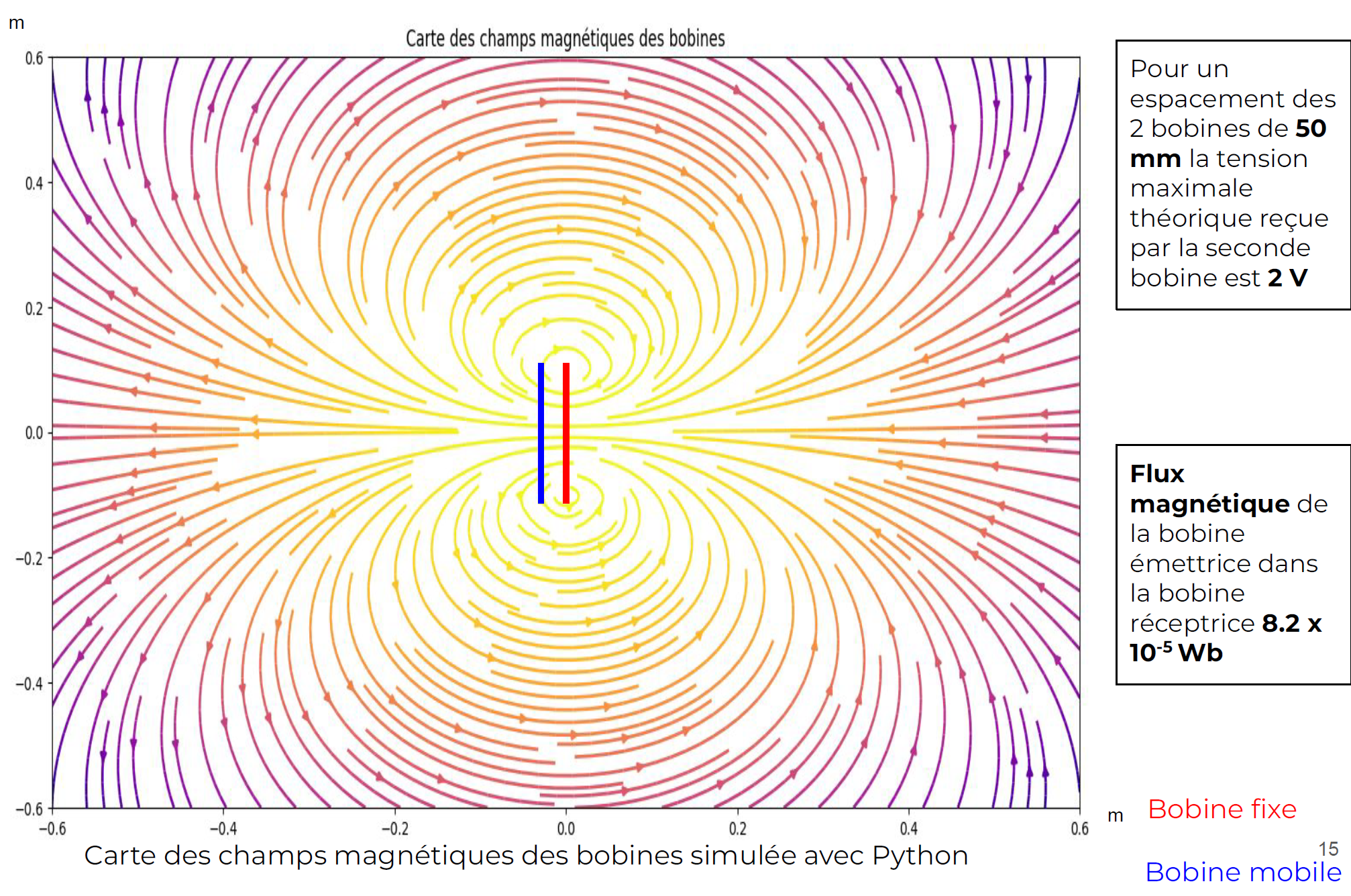
In our model, the fixed coil is subjected to an alternating current of 10 V peak-to-peak at 2.8 kHz. According to Maxwell-Ampère's equation: \( \nabla \times \vec{\mathbf{B}} = \mu_0 \vec{\mathbf{j}} + \mu_0 \epsilon_0 \frac{\partial \vec{\mathbf{E}}}{\partial t} \), a variable magnetic field is then created. A tension is induced in the second coil in accordance with Maxwell-Faraday's equation: \( \nabla \times \vec{\mathbf{E}} = - \frac{\partial \vec{\mathbf{B}}}{\partial t} \). The flux received by the mobile coil strongly depends on its relative position to the fixed coil. For a given distance between the centers of the two coils, the induced voltage is maximal when the two centers are aligned relative to the both coils orthogonal axis.
Feedback control
The mobile coil is motorized using a pulley-belt system with the pulley being driven by a NEMA 17 stepper motor. The position of the motor shaft is determined by a resolution of 200 steps per revolution with a precision of ± 5%. Depending on the induced voltage in the second coil, the Arduino board controls the motor to maximize the induced voltage along the two axes of the mobile coil. The motor is powered by an external stabilized power supply connected to the driver.
Signal Acquisition
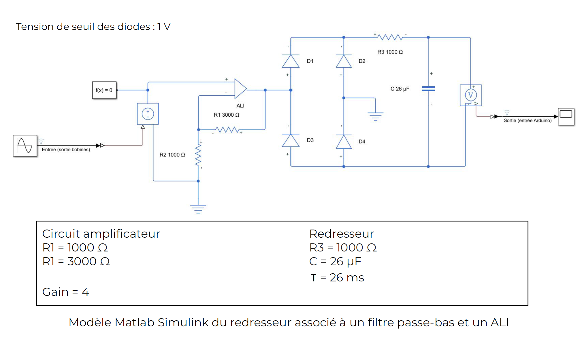
The acquisition chain of the system consists of four main elements. The signal at the terminals of the receiving coil is weak (in our model, the voltage in the fixed coil is intentionally low for safety reasons). An inverting amplifier, implemented with an operational amplifier and a ±15 V stabilized power supply, is used to amplify the raw signal from the receiving coil. A rectifier, constructed with a Graetz bridge (diode bridge), is employed to extract a positive signal. This signal is then smoothed using a low-pass filter to obtain a quasi-continuous signal. Subsequently, the Arduino board captures this signal, which is then analyzed to optimize the positioning of the mobile coil. For the sake of simplifying analysis, the Arduino board is controlled by a computer using Python.
III.2 - Coil Coupling
III.2.1 - Experimental Setup
III.2.2 - Modeling

We position the two coils optimally (both centers are aligned). For different frequencies, we measure the induced voltage in the receiving coil. We then plot the induced voltage against the frequency. It is observed that the received voltage is maximum at a frequency of 2.9 kHz, which explains the choice of this frequency for the rest of the project. However, it is important to note that this frequency depends on various intrinsic factors of coil construction (number of turns, geometry, etc.). The optimal frequency for the real system would likely be different.
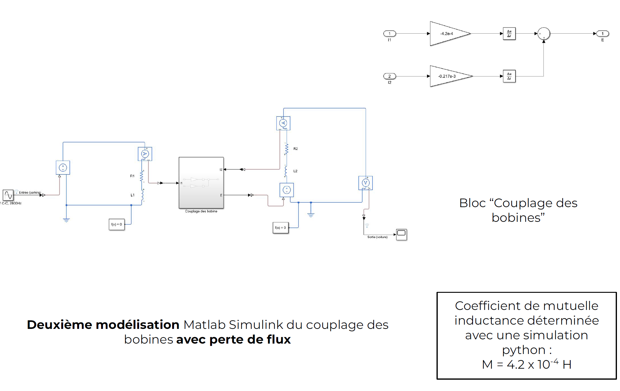
Matlab Simulink Model
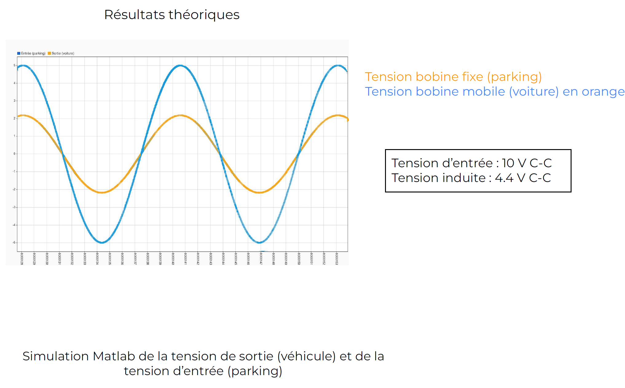
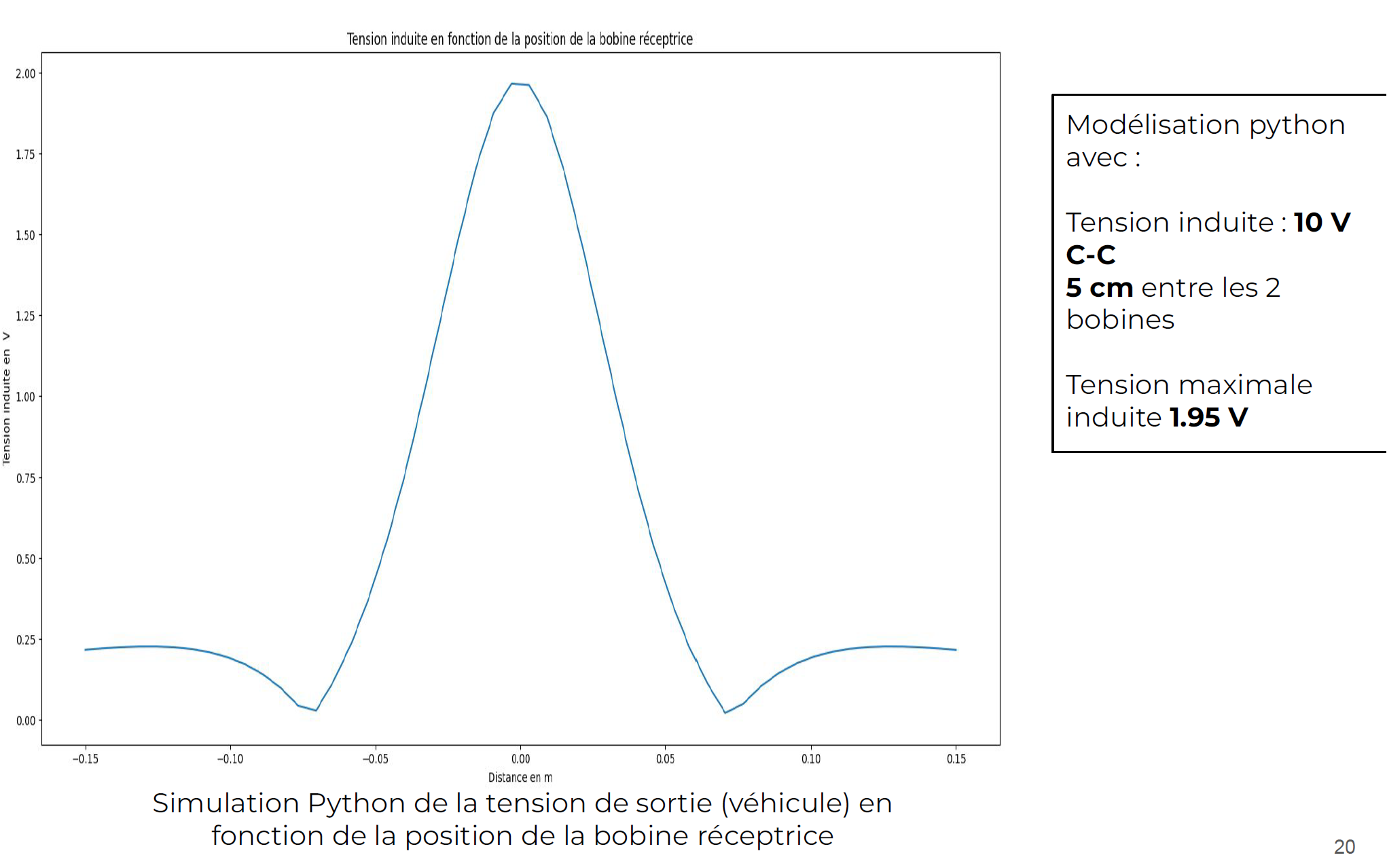
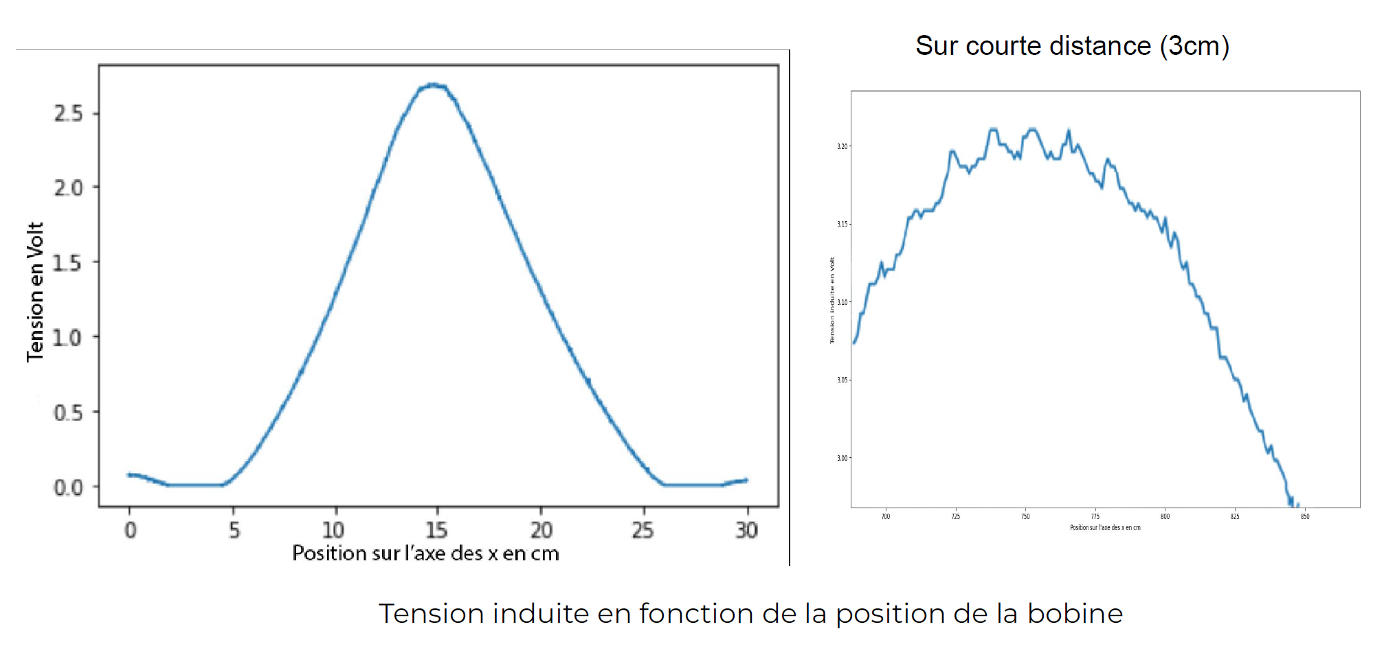
The induced voltage is maximum when the two coil centers are aligned (distance corresponding to 0.00 cm). However, it is interesting to note that beyond a certain distance between the two coil centers, the induced voltage in the mobile coil increases again. This is due to the folding of magnetic field lines in the second coil more optimally when the coils are no longer superimposed.
III.2.3 - Conclusion
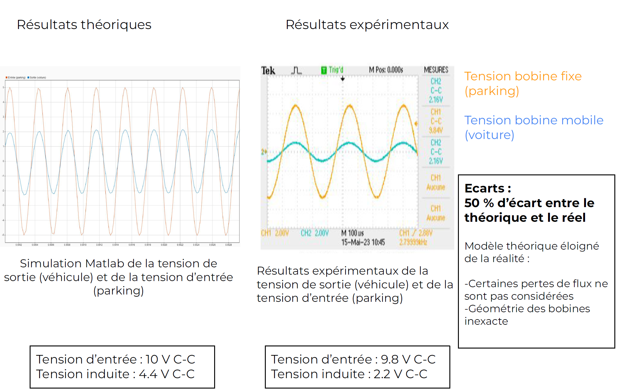
The discrepancy between the model and reality is largely due to simplifications made for presentation purposes.
III.3 - Signal Acquisition
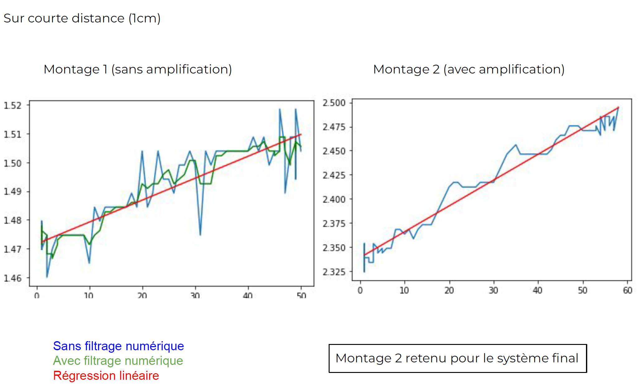
The first model did not include amplification before signal processing. The signal turned out to be extremely noisy, making the model less accurate. Therefore, we decided to include a non-inverting amplifier at the output of the receiving coil.
III.3.1 - Circuit Sizing
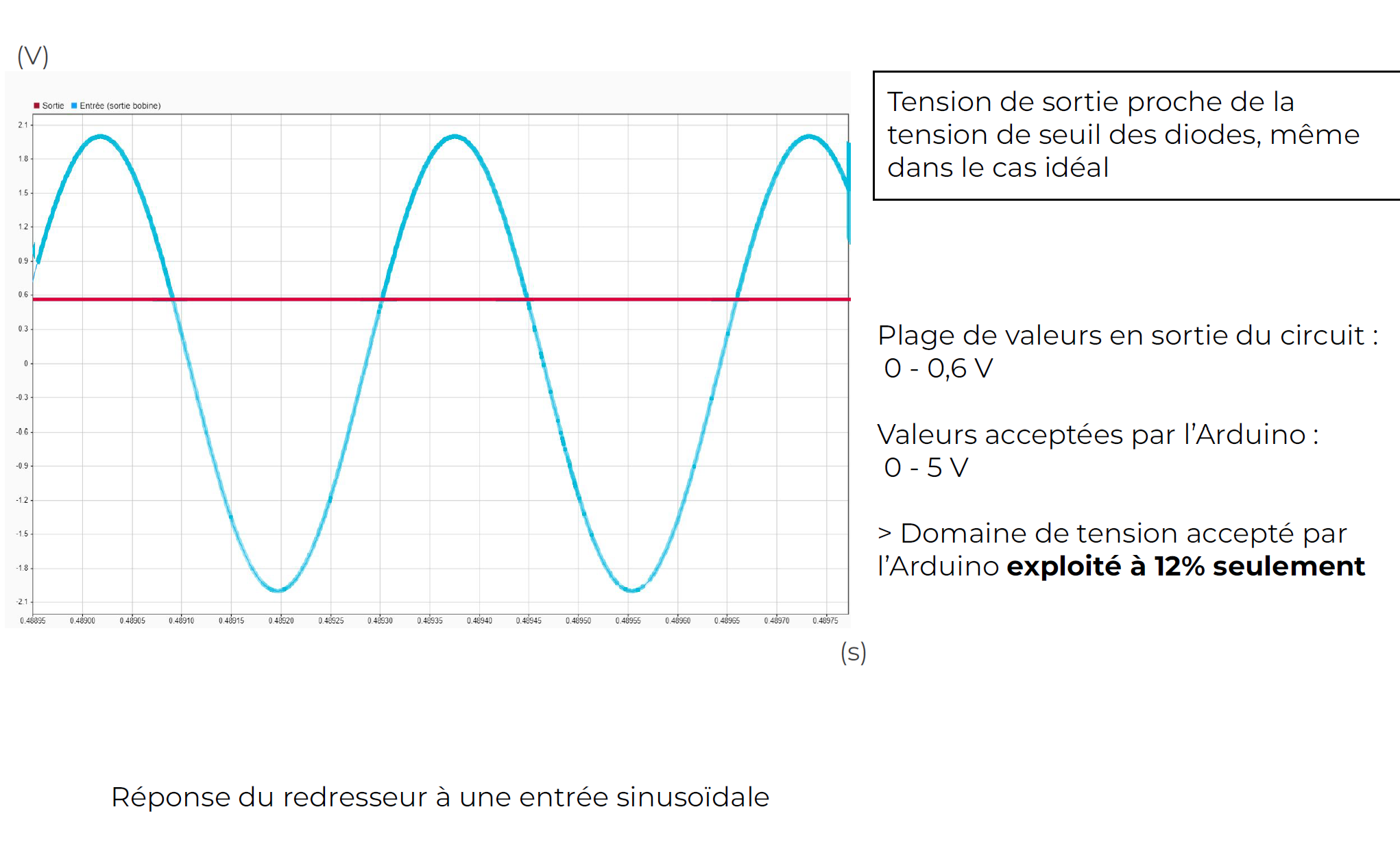
Amplifier Implementation
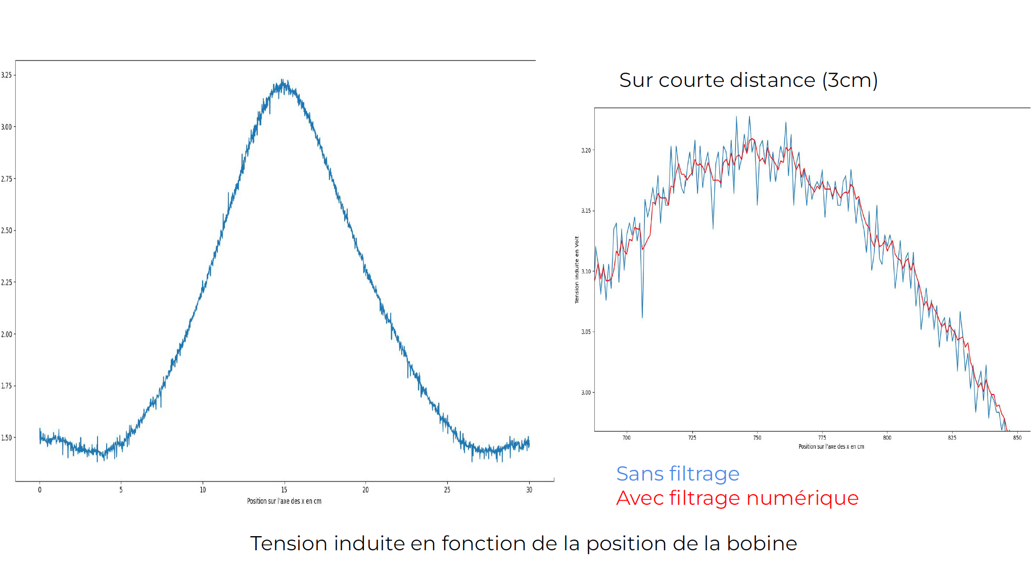
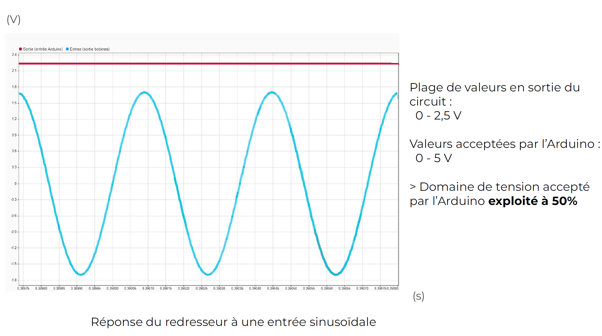
We use a digital low-pass filter implemented with the Arduino board to smooth the signal. The final circuit used is as follows.
So, the Arduino board exploits 50% of its measurement range. The signal is less noisy with the non-inverting amplifier.
Finally, for a coil displacement of 1 cm, the regression of the voltage change with displacement is qualitatively much more accurate.
III.4 - Discrete Control
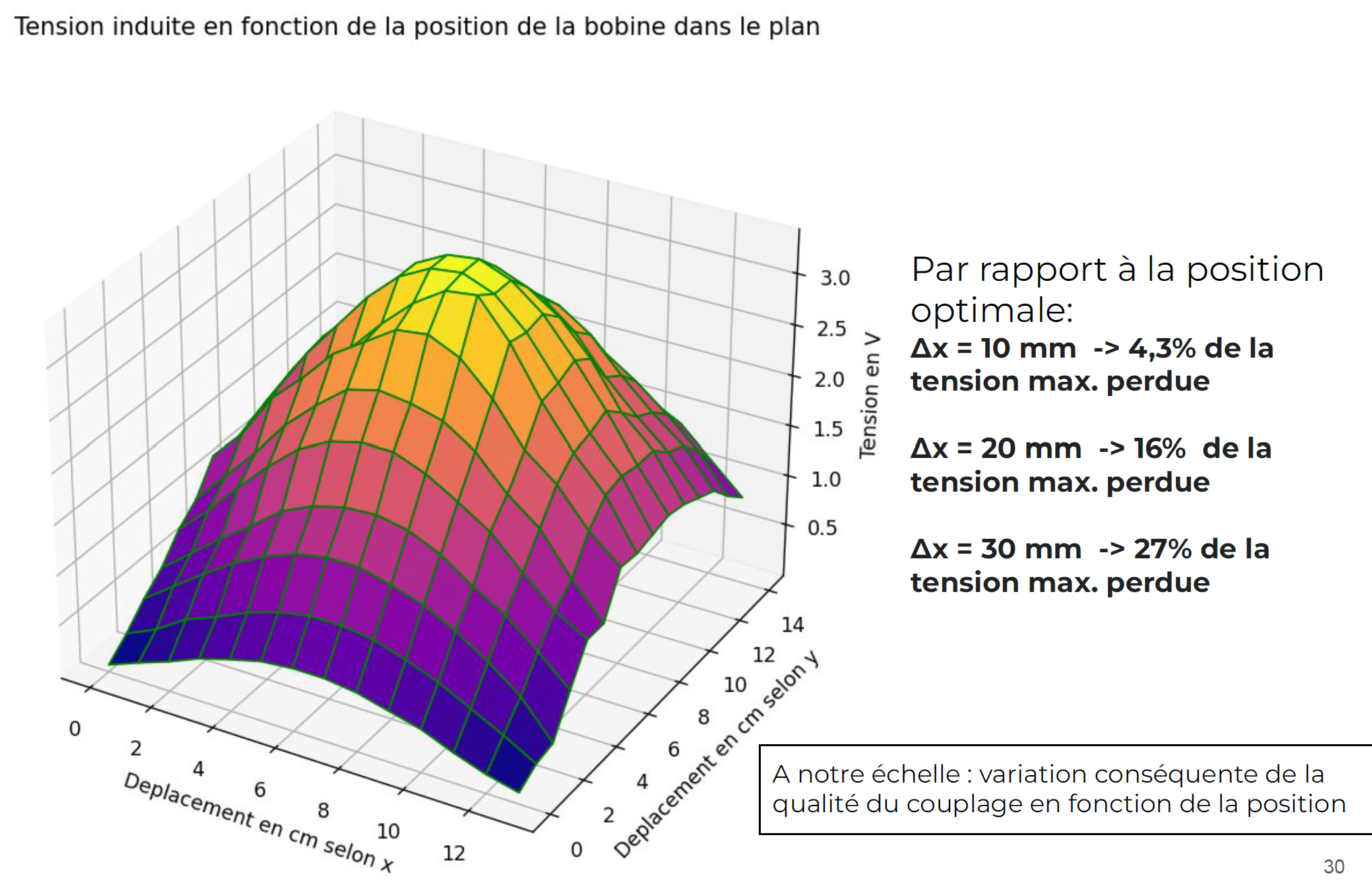
We measured the induced voltage in the receiving coil as a function of its position in the plane. The following graph shows the optimal coil positions. Also, a variation of 30 mm in the distance between the two coils results in a 27% variation in the induced voltage, demonstrating the relevance and importance of coil positioning.
III.4.1 - Working Principle
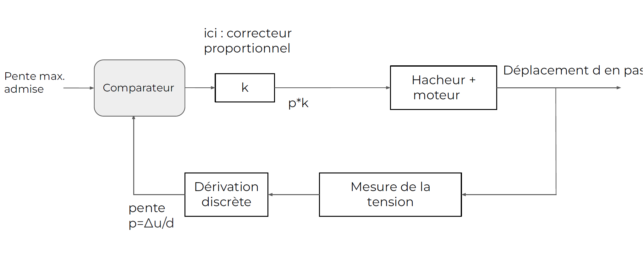
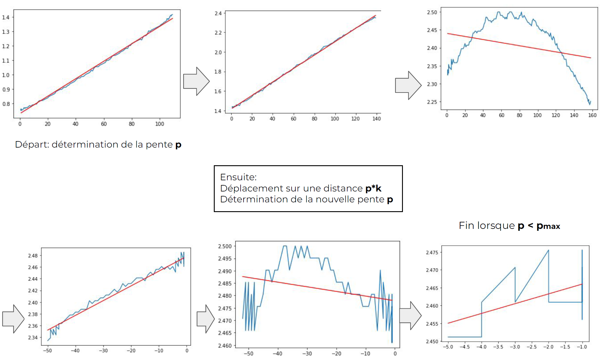
We decide on a maximum slope (slope of induced voltage versus coil displacement): this is the setpoint for control. The controller is initially a pure gain k, determined experimentally. The chopper + motor system causes a coil displacement of d in steps. This displacement of the receiving coil leads to a change in the induced voltage, which is measured and processed by the previously described system. Using a discrete derivative implemented in the Arduino board, we obtain the slope of the induced voltage versus coil displacement. This is the feedback of the control system.
III.4.2 - Practical Tests
Step-by-Step Process
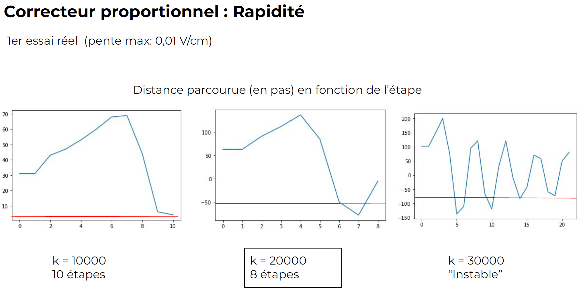
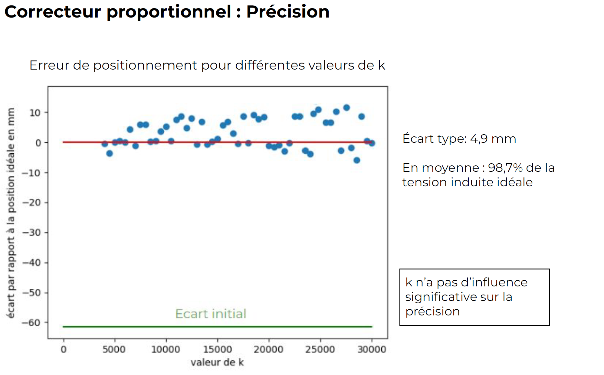
Impact of Controller Gain on System Performance
IV - Conclusion
This project, which partly shaped our work in preparatory class, allowed us to apply theoretical knowledge we learn in class and personally put into practice what we learn during practical work. It taught us how to manage a project from start to finish, with all the complications it entails, whether in terms of knowledge, practical aspects, or simply project organization.
V - Project Timeline
- March 2022: Initial research on induction charging in the automotive field. Experiments on Helmholtz coils in the laboratory led to the decision to focus on the relative positioning of the coils.
- June 2022: Discussions with engineers who have worked on the subject, providing information on the context and dimensions of the system. Start of prototype design.
- September 2022: Design of coils used in the prototype. Initial experimental measurements of induced voltage as a function of position and frequency.
- October-November: Theoretical modeling of coils, comparisons with experimental results. Connections of the Arduino board and stepper motors for precise coil positioning.
- December 2022: Sizing and assembly of an initial rectifier, converting the alternating signal into a continuous signal that can be read by the Arduino. Programming of a serial communication system between the Arduino and a computer using Python to facilitate movement and measurements.
- January - February 2023: Development of several programs attempting to automatically position the coils, with unsatisfactory results due to imprecise measurements: creation of a new rectifier circuit using an amplifier, initially dimensioned in Matlab.
- March 2023: Implementation of the discrete control system for positioning and adjustments of the proportional controller.
- May 2023: Search for alternative solutions for positioning. Measurement of induced voltage as a function of position in two dimensions.
VI - Project-Related Documents
- NEMA 17 Motor DatasheetDatasheet
- PDF Presentation © 2023 Paul Guillemin Victor Sin SohnPresentation